


2018CTBUH学会国内排名前列:揭秘超高层面纱下的结构之美

扫描到手机,新闻随时看
扫一扫,用手机看文章
更加方便分享给朋友


迪拜时间10月22日,2018 CTBUH 国际高层建筑与都市人居会议在阿联酋举行。作为中国超高层建筑设计的先进实践者-AUBE欧博设计董事副总经理、EN结构中心总经理黄用军先生及AUBE欧博设计结构中心EN2室副总监何远明先生受邀出席,与千余位来自全球高层建筑设计领域的专家学者进行了学术交流,并发表演讲,引发行业内关注。(点击查看现场实录)
本期“欧·TALK”邀请到了黄用军先生,首次在国内分享演讲,满满干货,以飨同行!
雨后春笋,拔地而起——
华润集团总部大楼
Introduction

建筑高度:400m
结构高度:331.5m
建筑高宽比:5.5
核心筒高宽比:11
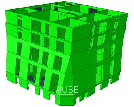
华润集团总部大楼,建筑高度400m,坐落深圳后海中心区核心位置,是深圳湾总部基地的重要组成。建筑造型独特,酷似一颗破天而立的竹笋。与一旁的华润深圳湾体育中心“春茧”共同寓意为 “雨后春笋”。
The China Resources Headquarter Tower with building height of 400m is located in the Shenzhen Bay of Shenzhen City, as an important component of the super headquarters base of Shenzhen Hou Hai. Its architectural style is unique and original, which resemble a narrow-topped Spring Bamboo. Next to it is the China Resources Shenzhen Bay Sports Center, “spring cocoon”, these two symbolizes “spring shoots after the rain”.

华润集团总部大楼采用密柱外框框架-核心筒结构,没有设置加强层。外框共有56颗柱,密柱兼做幕墙龙骨。
Close column frame and core tube system is adopted without strengthened stories.
There are 56 columns in the outer frame, size shown subsequently. The largest thickness of the tube shear wall is 1450mm at the bottom.

建筑共设有四层地下室。B1夹层由商场通往下沉广场,同时也成为出地铁顾客的入口大堂。B1层可直达地下商场以及博物馆。B2层是机电层,设置有装卸区域。B3和B4层则主要为停车场。
The basement is consist of 4 levels. B1 mezzanine which opens up to the Sunken Plaza lined by retail and provides a continued entrance lobby for some of the people arriving from the Metro. The B1 level provide direct connection the underground retail esplanade of the master plan as well as the Museum. It is the primary access point to the tower from the metro station. Level B2 is mechanical level with loading and level B3 and B4 are car park levels.
首层平面为环形,造型对称,按南北、东西划分为大小相同的四部分。
With its circular plan the ground lobby is symmetrical and organized in quadrants and engages equally with north, south, east and west.

1区办公层位于5~13层,较大无柱空间约17~18m。
2区办公层位于15~23层,较大无柱空间约16~18m。
Zone 1 is located between levels 5~13 and has column free space spans ranging from approximately 17 meters to 18 meters.
Zone 2 is located between levels 15~23 with column free space spans ranging from 16 meters to 18 meters.

3区办公层位于28~36层,较大无柱空间约18~17m。
4区办公层位于38~46层,较大无柱空间约17~15m。
Zone 3 is located between levels 28~36 and has column free space spans ranging from approximately 18 meters to 17 meters.
Zone 4 is located between levels 38~46 with column free space spans ranging from 17 meters to 15 meters.

5区办公层位于50~61层,含8个甲级办公楼层、2个行政办公层,1个商务中心层以及餐厅层。
Zone 5 office floor is located between level 50~61. It consists of 8 levels of typical grade A office space, 2 levels of VIP executive office floors, a business center level and a dining level.

华润办公区中庭剖面图
华润办公区中庭位于50~61层,有连续10层的楼板开洞,楼层梁隔层布置。因此,跨层柱具有较大的长细比,其稳定性是一个关键问题。
The CR office is between level 50~61. The continuous ten-storey floor is partially open, and the floor girder partition is arranged, so the cross-storey column has a larger slenderness ratio, which has a greater impact on the stability of the column.

空中大堂位于66层,据地高度331.5m,为70m高的钢网壳结构椎体。这是一个具有360度全景景观的多功能宴会厅,其上部为钢网格的塔尖。空中大堂与下面两层康乐设施层相连,可通过64层的空中大堂接待层的电梯到达或通过楼层北侧贯穿三层中庭的装饰景观楼梯到达。
The Sky Hall is located on level 66 at 331.5 meters above ground. A 70m high conical steel latticed shell is adopted. It is an event space with a 360 degree view and is capped by the diagonal grid structure of the spire. The Sky Hall Level is connected to two levels of amenities below. It is accessed elevators at the Sky Hall Reception Level 64 or by decorative grand stair at the north side of the floor spanning an atrium connecting all three levels.
亮 点 与 难 度
Highlights or nodus
风 荷 载
Wind load
荷载规范规定,深圳10年的基本风压为0.45 kN/m2,50年的基本风压为 0.75 kN/m2 , 构件强度设计采用规范50年基本风压的1.1倍风荷载
由于华润总部大厦有400m高,体型较为特殊,且周边有不少高层建筑环绕,因此,规范风不能确保为最不利风荷载分布。在RWDI和SCUT做了风洞对比试验。结果显示,两家风洞试验单位的独立试验结果相似度很高,结果可信。
The basic wind pressure in Shenzhen is 0.45 kN/m2 in 10 years, 0.75 kN/m2 in 50 years, and the strength design uses 1.1 times of the 50 year benchmark wind pressure in the Chinese load code.
As the CR tower up to 400m, it has special body shape and lots of high-rise buildings around, so the wind load distribution of code may not cover the worst wind load. Contrast tests were made by RWDI and SCUT. Wind tunnel test results show that the analysis results of two independent wind tunnel test units are more consistent, and the wind tunnel test results are reliable.
抗 侧 力 体 系
Lateral Resistance System
为增加冗余度,结构必须具有多重抗侧力体系来抵抗风和地震等水平荷载作用。本工程中,外框的剪力分担比少于5%,而规范要求最少为10%。由于没有设置加强层,外框柱截面很小,刚度较弱,很难分担更多的剪力,因此,设计中采用核心筒来承担100%的水平剪力,并乘以1.1的放大系数以保证核心筒有足够的承载能力。同时,调整外框的水平剪力不小于总剪力的10%,确保外框有一定的剪力分担能力。
To increase structural redundancy, the structure must have multiple system to resistant the lateral loads such as seismic force and wind loads. In this project, the shear sharing ratio of outer frame is less than 5%, however 10% is the minimum value required by code. As the close column frame without strengthened stories has weak frame axial stiffness, it’s hard to meet the requirements. So, the core tube shear wall are set to bear all lateral shear, which is magnified to 110%, to ensure the tube has sufficient bearing capacity. At the same time, the shear of the frame is adjusted to 10% to ensure limited capacity to lighten the burden of the tube.
桩基设计
Pile Design
根据水文地质条件,方案阶段比较了人工挖孔桩和冲(钻)空灌注桩两种桩型。
初设阶段,桩基设计采用56颗人工挖孔桩.根据平安金融中心的工程经验,桩基设计在施工图阶段调整为44颗人工挖孔桩,桩端设置扩大头,核心筒下承台厚度为3.5m,外围承台厚度为2.5m。
According to geological and hydrological conditions, comparisons between man-dug caisson and bored pile are made in the SD. 56 man-dug caissons is adopted in the DD. According to the engineering experience of Pingan IFC, pile layout is changed to 44 man-dug caissonswith an expanding bottom in the CD. The cap thichness is 3.5m under the core tube,and is 2.5m for the other.
搭 接 墙 转 换
Lapping Wall and Oblique Wall
“春笋”大楼核心筒墙体转换了两次。首层核心筒的外轮廓是方的,到4层及以上则通过倒角来适应外轮廓的变化。 在2层~3层设置搭接墙予以转换。
Same for the core tube, two transform are emerged as shown. In the 1F, the outline of tube is square. Four corner are cut 3041mm going to the 4F, leaving 2~3F to realize the lapping.

到高区,核心筒的外轮廓由切角方形变为方形,通过斜墙转换来实现。
Up to the top zone, the outline of the tube is changing from tangential square to square. Using oblique wall conversion to make this transformation.
斜 墙 转 换
Oblique Wall Transform

在48~49F设置斜墙变换,高度240.95~256.45m,在竖向荷载作用下斜墙会产生水平力,因此板和梁是将该水平力传递到相邻竖向构件的主要媒介。外框柱的剪切刚度远小于核心筒的剪切刚度,因此大部分水平力可以在核心筒内获得自平衡。理论上,外框的楼板可能会出现少量的水平力。因此,整层楼板都需要采取加固措施。
Oblique wall transform is set on the 48~49F, at 240.95~256.45m. Horizontal force is produced by the oblique wall under vertical load, so slab and beam is the main medium to transmit the force to neighbouring vertical members. Shear stiffness of close columns is much smaller than that of the core tube, so most force can get self-balance in the tube. A small amount of horizontal force may appear in the outer frame slab theoretically. Strengthening measures should be made in the whole floor slab.
实际上,由于施工的原因,在斜墙完工时,核心筒中楼板和外框架还没有施工。此时的竖向荷载包括墙体自身的重力和施工平台的荷载(含施工活荷载)。一般来说,在施工过程中,外框架会比核心筒晚15~20层施工。斜墙出现在48层,整个建筑有66层。因此,需要验算核心筒全部建完,而斜墙位置还没有施工外框架梁板的情况。结果表明,核心筒剪力墙不能独自承担斜墙引起的水平力,连梁是承担水平力的关键构件。
Actually, the slab in the tube and the outer frame are not build when the oblique wall is completed for the reason of construction procedure. The vertical load is produced by the gravity of the wall itself and the load of construction platform, including the construction live load. Generally, the frame will be 15~20 floors later than the core tube during the construction. The oblique wall appears on the 48F, and the whole building is just 66F tall. This case that the tube is completed with no frame slab and beam at the oblique wall position is calculated.As the result shown,the oblique wall cannot support the load by itself without slab,and coupling beam is the key component.

通过参数分析,得出斜墙仅能承受6层左右的上部荷载,因此当核心筒达到56F时,必须封闭48F的外框架和核心筒楼板。
According to parameter analysis, the oblique wall can just afford 6 floors above, so the floor frame and slab of 48F must be completed when the core tube is up to 56F.
平 面 布 置
Plan Layout
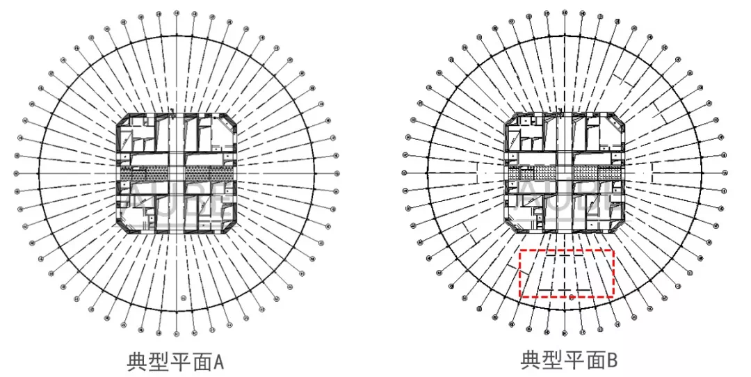
根据建筑平面,典型平面A为较佳选择。然而,不排除有部分业主会同时购买多楼层,此时户内楼层间的楼梯就很有必要。为考虑租售的方便,结构平面布置调整为平面B。
According to the architectural plan, plan A is an apparent choice. However, some owners may want to buy two floors or more. Stairs indoor would be necessary in this case. In consideration of the flexibility of sale and rental, some adjustments are made, shown as the plan B.
塔 冠 结 构
Cone top structure
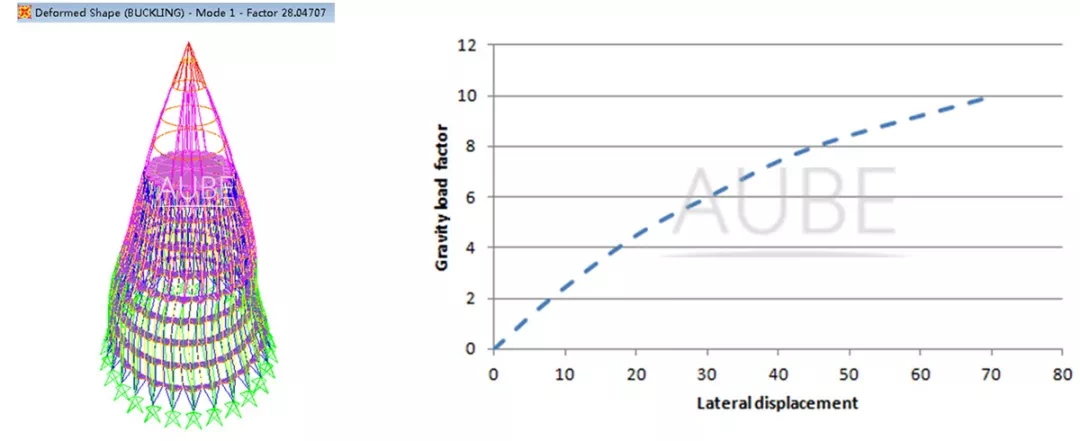
弹性特征值分析表明,在重力作用下临界特征值达到28,排名前列阶屈曲模态如上所示。
初始几何缺陷对网壳结构的稳定承载力有很大影响,在计算中应予以考虑。网壳结构的初始几何缺陷包括节点的安装偏差、杆的初始弯曲、杆对节点的偏心等。结果表明,当初始几何缺陷按较低阶屈曲模态分布时,初始几何缺陷是最不利的值,因此本工程计算中所施加的初始几何缺陷是基于一阶屈曲模态。
Elastic eigenvalue analysis shows that the critical eigenvalue reaches 28 under gravity, and the first instability mode under gravity is shown as above.
The initial geometric imperfections of various latticed shells have great influence on the stability bearing capacity and should be considered in the calculation. The geometric initial defects of reticulated shells include the installation deviation of joints, the initial bending of bars, the eccentricity of bars to joints and so on. The results show that the initial geometric imperfection is the most unfavorable value when the initial geometric imperfection is distributed according to the lowest order buckling mode, so the geometric initial imperfection imposed is based on the first order buckling mode.
完 全 偏 心 节 点
Totally Eccentric Joints

为了满足人们对豪华办公区无柱空间的想象,“春笋”大楼采用完全偏心节点。这是排名前列次将这种类型的节点用于高度达到400m的超高层建筑,是一个很大的挑战和创新。
如前所述,本工程中采用了大量的完全偏心节点,计算中的节点刚度是通过有限元模拟得到的,梁柱节点仅仅通过一个板带连接。因此,如何保证节点区具有可靠的传力路径和便于施工,是该节点设计的关键。
To meet people’s desire of column free space in a luxury office, totally eccentric joints are adopted. It’s the first time to use this kind of joints to a tall building up to 400m, which is a big challenge.
As mentioned before, lots of totally eccentric joints are used in this project. Joint stiffness input in the calculation model is simulated by finite element analysis. Just one slab zone is linked between the frame column and beam. How to make it have reliable path of force transmission and easy to construct is the key link.
交 叉 节 点
Intersection Joints
竹笋,两端小,中间大。外框在中间区域有56颗柱,但结构底部和顶部变窄了,因此需要减小柱的数量,由此产生了交叉柱节点。
一层为两根柱,而二层为三根柱,相交处节点区最小截面仅为比柱本身的截面要小很多。因此,细腰节点区如何支撑上部结构的所有荷载是本项目的一个重要课题。
A bamboo shoot, both ends are tiny and the middle is large. There are 56 columns in the middle zone, and it gets narrower on the top and the lower zone.
There are two columns in the first floor, and three columns in the second floor. The minimum cross section of joint area is much smaller than the cross section itself.How to support the upper part of the structure is the most important matter in this project.
多 柱 交 叉 节 点
Multi-column Intersection Joints
由于建筑的外立面是弧形的,因此形成交叉节点的柱不在同一个竖向平面内,节点区连接板错位,且连接板的数量较多,受力极为复杂。
结构底部通过交叉网格来实现柱距的调整,上下柱截面差别不大。上部楼层有3颗柱,下部楼层有2颗柱,而交叉节点区仅有1颗柱的截面尺寸大小,形成了一个细腰的结构。细腰导致轴向受力面积显著减小,且需要承担上部60多层结构的竖向荷载,因此,在经过对该节点区受力的重点分析后,我们找到了解决方案。
Since the façade of the building is curved, each intersecting bar is not in the same vertical plane. The connecting plates in the joint area are misaligned and the number of the junction plates is large which lead to complex force condition.
A big column grid is required at the bottom,and the transition is completed by the oblique grid. The section of the upper and lower column is not very different. There are 3 columns on the upper floor and only 2 columns on the lower floor, forming a fine waist at the intersecting joints of the bars. The fine waist leads to a significant reduction of the axial compression area. Special analysis for its load carrying capacity is required.
图示为节点区位置和受力示意,由于其立面为弧线,在节点区把面板设计为平面,节点区立面为直线,即圆弧线的割线。上、下柱理论上交于一点,即图中的理论柱中心(定位中心),而截面实际的中心与该交点存在一定的偏差,因此在上、下柱轴力作用下,节点区并不是轴心受力构件,会有弯矩存在。
节点区面内弯矩My产生的原因如图所示,节点区表现出受弯的受力特征,主要源于柱轴力在垂直面板方向的分量Fx所产生的弯矩,类似也会产生沿节点面板面外的弯矩Mx。柱C1和柱C3的内力在数值上会存在差异,形成力偶;在柱C2的Fy2分量的作用下,节点区会存在一定的扭矩Mz。因此,节点构造使节点区存在附加的弯矩和扭矩。计算发现,节点区因该弯矩产生的附加应力占到了节点轴向受压应力的40%,不容忽视。在节点设计时应全面考虑,确保结构安全。
Since the elevation is an arc, the panel is designed as a plane in joint zone and the elevation of the joint zone is a straight line, which is the secant of the arc line. The upper and lower columns theoretically intersect at one point, which is the theoretical center of the steel column. However, the actual center of the section has some deviation from the theoretical intersection. Therefore, under the axial force of the upper and lower columns, the joint zone is not an axially loaded member and will have some bending moments and torque moments.
The joint zone shows the mechanics characteristics under the bending moment action, mainly due to the bending moment generated by the component Fx of the column axial force in the direction perpendicular to the face panel. In the same way, the bending moment that is out of the plane of face panel of the joint zone will also be generated. The internal force in column C1 and column C2 will differ in value, forming a couple of forces: under the action of the Fy2 component of column C2, there will be some torque Mz in the joint zone. Therefore, the joint configuration causes additional bending moments and torques in the joint zone. It is found through calculation that the additional stress generated by the bending moment in the joint zone accounts for 40% of the axial compressive stress of the joint and cannot be ignored. The joint design should be fully considered to ensure the structural safety.
在-x向多遇地震工况下,应力云图和塑形应变图分别如图所示,构件拼接位置出现应力集中(实际施工对其进行平滑处理,可以消除),仅局部区域屈服,绝大部分仍处于弹性工作阶段。
In the load case of frequent earthquake at –x direction, the stress cloud diagram and plastic strain diagram are shown. Stress concentration occurs at the joint position of the components (which can be eliminated in actual construction by smoothing). Only part of area yielded and most of area still remain elastic working stage which meet the requirements of joint design.
在+y向罕遇地震作用下,应力和塑形应变如图所示。从图中可以看出,截面突变的位置出现了应力集中,仅局部屈服,绝大部分区域均处于弹性工作状态。节点区内部的应力和塑性应变云图如图所示,可以看出,节点在罕遇地震作用下处于弹性工作状态。
Under the action of rare earthquake at +y direction, the stress and plastic deformation are shown. It can be seen from the figure that the stress concentration occurs at the position where the cross section is changed, and only local yielding happened, and most of regions still remain in elastic working condition.
在柱底端施加稳定承载力,上柱端约束三向位移,对节点进行等强节点验算,应力和塑形应变云图如图所示,可以看出,除细腰部有稍许屈服外,绝大部分处于弹性工作状态,满足节点设计要求。
A stable bearing capacity is applied at the bottom end of the column. The three-direction displacement is constrained at the top end of the column. The equal-strength joint check is performed on the joint.
It can be seen that most area of the joint is in elastic working condition except that the thin waist slightly yields, which satisfy the requirements of joint design.
总 结
Conclusions
试验和有限元分析结果表明,节点在设计荷载作用下处于弹性工作状态,各板件厚度设计基本合理,可有效传递竖向荷载。节点具有良好的承载能力、刚度和延性。
有限元分析结果与试验结果一致,在设计荷载作用下具有较高的可信度。
对节点进行的构造简化,会使节点承受附加的内力。在工程中,节点区面板的处理引起的附加应力约占到初始应力的40%,不容忽视。
节点设计应全面分析其传力路径的可靠性和节点细部构造可能产生的影响,方能确保设计安全。
The results of experiment and finite element analysis show that the joint is in elastic working condition under the action of design load, and the thickness of each plate is basically reasonable which can transfer the vertical load effectively. The joint has good bearing capacity, stiffness and ductility.
The results of the finite element analysis are consistent with the experimental results and have a high degree of confidence under the action of design loads.
The simplification of the configuration of the joints will bring additional internal forces to the joints. In this project, the additional stress caused by the treatment of the face panel of the joints accounts for 40% of the initial stress and cannot be ignored.
The reliability of force transfer path and the possible influence of the detailed configuration of joints should be comprehensively analyzed during the joint design to ensure the safety.
特别鸣谢:黄用军先生、何远明先生
欧博设计供稿
声明:本文由入驻焦点开放平台的作者撰写,除焦点官方账号外,观点仅代表作者本人,不代表焦点立场。